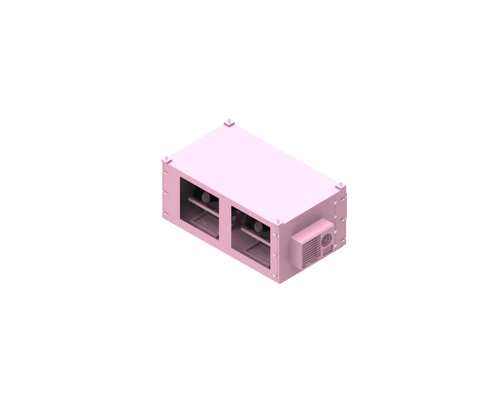
A good sheet metal fabrication drawing removes ambiguity before laser cutting, CNC bending, welding, finishing, and assembly begin. For custom enclosures, outdoor projector housings, network cabinets, and climate-controlled equipment cabinets, the drawing must communicate dimensions, material, thickness, bends, openings, mounting, access, cooling, finish, quantity, and functional requirements—not just the outside shape.
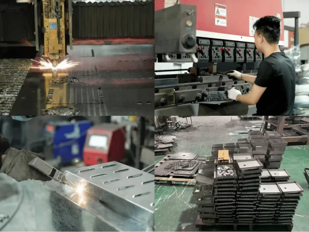
What is Sheet Metal Fabrication?
Sheet Metal Fabrication is the process of turning flat metal sheets into finished parts, cabinets, brackets, panels, and enclosures through cutting, bending, welding, finishing, and assembly. A useful drawing must define the geometry and manufacturing requirements clearly so the supplier can quote, produce, inspect, and assemble the part correctly.
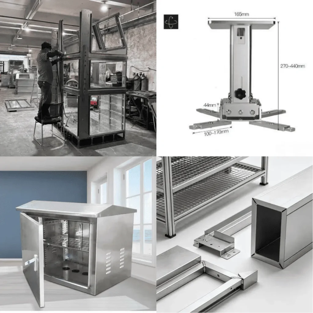
Practical Meaning for Custom Enclosures
In real projects, Sheet Metal Fabrication is not only about making a flat plate or bent bracket. For ShiRui, it often involves custom sheet metal enclosures, outdoor projector enclosures, outdoor network cabinets, climate-controlled equipment cabinets, and project-specific metal housings.
A fabrication drawing should connect the finished product requirements to the manufacturing process:
- Laser cutting needs accurate outlines, hole positions, slots, vents, and cutouts.
- CNC bending needs bend locations, bend directions, angles, and final formed dimensions.
- Welding needs joint locations, assembly relationships, and appearance requirements.
- Surface finishing needs material, coating, color, corrosion requirements, and visible surface expectations.
- Assembly needs doors, locks, hinges, seals, brackets, rails, trays, cable entries, and internal component locations.
- Final inspection needs critical dimensions, tolerances, revision information, and quantity requirements.
For enclosure projects, the drawing should be developed around the actual equipment and application, not only the outside cabinet size. Internal space, mounting method, heat load, cable routing, access direction, maintenance clearance, and installation environment all affect the final sheet metal design.
ShiRui Pro Tip: I always recommend starting with the equipment and installation conditions first. If the drawing only shows an empty box, important details such as airflow, cable entry, door access, and mounting strength may be discovered too late.
How Does Sheet Metal Fabrication Work?
Sheet Metal Fabrication works by converting approved drawings and specifications into manufactured parts through staged processes such as laser cutting, bending, welding, grinding, surface finishing, assembly, and inspection. Each drawing detail affects a real production step, so unclear dimensions or missing notes can delay quotation and manufacturing.
Video Guide: Explore our custom sheet metal enclosure fabrication for outdoor equipment applications. This video showcases the metal housing structure and manufacturing capabilities for OEM/ODM projects, including custom sizes, materials, and enclosure designs.
From Drawing to Finished Metal Product
A drawing is the communication bridge between design intent and manufacturing execution. When ShiRui reviews a custom enclosure project, each drawing item is checked against the manufacturing route.
- Requirement review
Confirm what the part or enclosure is used for, where it will be installed, what equipment it contains, and what functional requirements it must meet. - Material and thickness confirmation
Galvanized steel, aluminum alloy, 201 stainless steel, and 304 stainless steel may be considered depending on corrosion risk, strength, weight, heat dissipation, installation environment, and budget. - Laser cutting preparation
Profiles, holes, slots, ventilation openings, cable entries, connector cutouts, fan openings, optical windows, and mounting holes are reviewed before cutting. - CNC bending review
Bend direction, bend sequence, bend angles, formed dimensions, and adjacent bend relationships are checked. Bend allowances, K-factors, bend deductions, and tooling-specific values should be confirmed by the manufacturer for the actual process. - Welding and grinding review
Welded parts, weld locations, appearance requirements, continuous or intermittent welding needs, and finishing areas must be defined where relevant. - Surface finishing
Powder coating, stainless steel finishing, anti-corrosion treatment, custom colors, logos, or markings should be specified when required. - Assembly and inspection
Doors, hinges, locks, internal trays, rails, brackets, seals, cooling components, and fasteners are checked against the drawing and application requirements.
ShiRui Pro Tip: I treat every fabrication drawing as a production instruction. If a hole affects laser cutting, a bend affects forming, a weld affects finishing, or a door affects maintenance, it should be clear before production starts.
How to do sheet metal drawings?
To do sheet metal drawings correctly, show the finished formed part, critical 2D views, units, overall dimensions, material, sheet thickness, bend details, holes, cutouts, tolerances, welding, finish, mounting points, assembly notes, and revision data. The goal is to make manufacturing intent clear without over-dimensioning or creating conflicts.
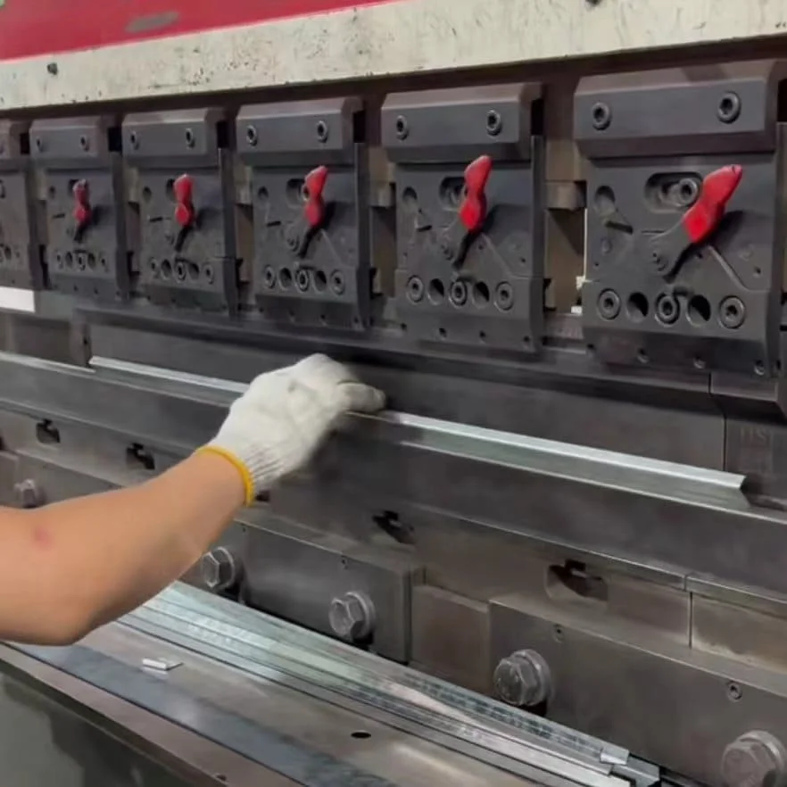
Drawing Preparation Checklist
A strong sheet metal drawing should be clear enough for quotation, production, and inspection. It should not rely only on a 3D model for critical dimensions.
Use one consistent unit system throughout the drawing. For ShiRui projects, dimensions are commonly reviewed in millimeters, but customers may use other units if they are clearly identified. Avoid mixing millimeters and inches unless both are explicitly labeled.
Essential drawing items include:
- Part name and drawing number
- Revision number and revision date
- Units
- Overall length, width, and height
- Door, panel, and internal usable space dimensions
- Material type
- Material thickness for each component where required
- Bend locations, bend directions, and bend angles
- Final formed dimensions
- Hole locations from clear datums or centerlines
- Hole types, including through holes, threaded holes, countersunk holes, counterbored holes, slots, or special cutouts
- Cable openings, ventilation openings, connector cutouts, fan openings, lock holes, handle openings, sensor openings, display windows, and optical windows
- Critical tolerances where function requires control
- Welding locations and appearance requirements
- Surface finish and color reference when available
- Mounting points and installation interfaces
- Door opening direction and access requirements
- Quantity and assembly notes
Avoid duplicate or conflicting dimensions. More dimensions are not always better. Critical functional dimensions should receive the greatest attention, while unnecessary repeated dimensions should be removed.
ShiRui Pro Tip: I prefer drawings that define holes and cutouts from clean datum edges or centerlines. Long chains of dependent dimensions increase accumulated error and make both fabrication and inspection harder.
How to draw fabrication drawing?
A fabrication drawing should be drawn from the manufacturer’s point of view: what must be cut, bent, welded, finished, assembled, and inspected. Start from the final part requirements, then add views, datums, dimensions, material, thickness, bend information, holes, tolerances, finish, assembly relationships, and revision control.
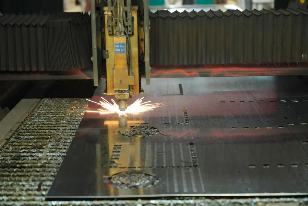
Manufacturer-Focused Drawing Workflow
A good fabrication drawing is not simply a CAD export. It is a controlled manufacturing document that removes uncertainty.
Follow this practical workflow:
- Confirm the finished requirement
Define the part function, equipment dimensions, equipment weight, indoor or outdoor use, installation method, quantity, material preference, surface finish, environmental conditions, and maintenance requirements. - Create the formed part views
Show front, side, top, section, detail, and isometric views as needed. For complex enclosures, include internal views and assembly views. - Add critical dimensions
Show overall dimensions, door sizes, panel sizes, internal usable space, mounting dimensions, and interface dimensions. - Define material and thickness
Identify the required metal and thickness. ShiRui has used sheet metal thicknesses from approximately 1.2 mm to 4.0 mm in different enclosure projects, but the correct thickness depends on size, load, rigidity, material, mounting method, and reinforcement design. - Specify bends
Communicate bend location, direction, angle, final formed dimensions, and relationship between adjacent bends. If a flat pattern is included, it should correspond to the final formed part. - Locate holes and cutouts
Dimension mounting holes, cable entries, vents, fan openings, air-conditioner openings, lock holes, optical windows, and connector cutouts from clear datums. - Add manufacturing notes
Include welding, grinding, surface finish, assembly, cable routing, access, and inspection requirements where applicable. - Control revisions
Every drawing should identify the latest revision so the supplier does not manufacture from outdated information.
ShiRui Pro Tip: I always check whether the 2D drawing and 3D model tell the same story. If the flat pattern, formed view, and assembly model do not match, the project should be clarified before quotation.
Is sheet metal fabrication difficult?
Sheet Metal Fabrication is manageable when the drawing is complete, but it becomes difficult when material, thickness, bends, tolerances, hole positions, welding, finish, mounting, cooling, or assembly requirements are missing. The challenge is not only drawing the shape; it is communicating how the part must function and be manufactured.
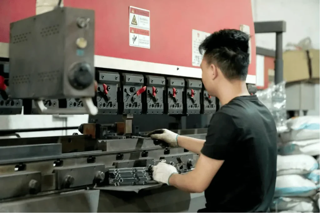
What Makes Fabrication Simple or Difficult
The difficulty of Sheet Metal Fabrication depends on part geometry, material, thickness, bend complexity, tolerance requirements, weld appearance, finishing expectations, assembly accuracy, and application environment.
Based on our internal data and market analysis, here is the breakdown:
| Factor | Lower Complexity | Higher Complexity |
|---|---|---|
| Geometry | Simple flat or single-bend panels | Multi-bend enclosures with internal partitions |
| Material | Common material with clear specification | Material not specified or unsuitable for environment |
| Thickness | Appropriate for size and load | Too thin for rigidity or too thick for forming needs |
| Holes and cutouts | Clearly located from datums | Unclear, chained, or conflicting locations |
| Tolerances | Applied only to critical interfaces | Tight tolerances applied everywhere |
| Welding | Few clearly marked welds | Many unclear weld joints and finish expectations |
| Surface finish | Standard finish clearly specified | Outdoor corrosion needs not defined |
| Assembly | Simple single part | Doors, hinges, locks, seals, fans, trays, rails, and wiring |
| Thermal design | Cooling planned before fabrication | Cooling openings added after layout is finalized |
| Revision control | Current drawing clearly identified | Multiple versions without approved revision |
Custom outdoor projector enclosures and climate-controlled cabinets are usually more complex than simple brackets because they must consider optics, airflow, weather exposure, internal equipment, service access, and mounting safety.
ShiRui Pro Tip: I do not consider complexity a problem by itself. The real problem is hidden complexity. If we know the function, environment, equipment, and assembly requirements early, we can review the structure before fabrication begins.
Key Features & Comparison
A useful sheet metal fabrication drawing does more than show size. It compares and clarifies the manufacturing-critical features that affect cutting, bending, welding, finishing, assembly, quotation, and inspection. The best drawings separate critical requirements from general information so the manufacturer can identify risks before production.
Video Guide: Discover our sheet metal fabrication capabilities for custom equipment enclosures and metal housings. We support OEM/ODM manufacturing with flexible enclosure sizes, materials, structures, and designs for outdoor and industrial applications.
Drawing Elements That Affect Manufacturing
Based on our internal data and market analysis, here is the breakdown:
| Drawing Feature | Why It Matters | Typical Risk If Missing |
|---|---|---|
| Units | Prevents dimensional misunderstanding | Incorrect part size |
| Overall dimensions | Defines product envelope | Enclosure does not fit equipment or site |
| Material | Affects strength, corrosion, weight, and cost | Wrong material quoted or produced |
| Sheet thickness | Affects rigidity, bending, welding, and load capacity | Weak panels, deformation, or quotation delay |
| Bend direction and angle | Controls final formed geometry | Part bends the wrong way or does not assemble |
| Hole locations | Guides laser cutting and inspection | Misaligned mounting or connector interfaces |
| Hole types | Defines machining or fastening needs | Threaded or countersunk features omitted |
| Critical tolerances | Controls functional interfaces | Loose fit or unnecessary high cost |
| Welding notes | Defines joint and finishing expectations | Unclear assembly and surface defects |
| Surface finish | Controls corrosion resistance and appearance | Wrong coating, color, or protection level |
| Door direction | Affects installation and maintenance | Door opens into obstruction |
| Cable entries | Affects wiring and sealing | Cable routing conflict or water ingress risk |
| Cooling openings | Supports thermal management | Overheating or sealing problems |
| Revision number | Controls document version | Old design manufactured |
For ShiRui enclosure projects, key features often include door quantity, access direction, hinge and lock position, internal trays, mounting rails, cable glands, fan or air-conditioner cutouts, filters, heaters, sensors, and removable panels.
ShiRui Pro Tip: I ask customers to mark which dimensions are truly functional. This helps us focus manufacturing control where it matters instead of increasing cost with tight tolerances on non-critical dimensions.
Cost & Buying Factors
Cost depends on material, thickness, size, complexity, quantity, cutting time, bending difficulty, welding, grinding, finishing, assembly, thermal components, packaging, and inspection requirements. A clear drawing helps the supplier quote accurately because it reduces assumptions, rework risk, and technical clarification during manufacturing review.
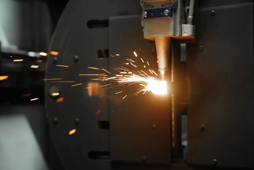
What Buyers Should Prepare for Quotation
For purchasing teams, OEM buyers, contractors, equipment manufacturers, engineers, and AV integrators, the RFQ should provide enough information for technical and commercial review.
Include the following where available:
- Required quantity
- Prototype quantity if applicable
- Production quantity
- Part name or enclosure name
- Drawing number and revision
- 2D drawing
- 3D model if available
- Material requirement or material preference
- Sheet thickness requirement if known
- Surface finish requirement
- Color reference when available
- Indoor or outdoor use
- Equipment model and specification sheet
- Equipment dimensions and weight
- Installation method
- Mounting interface
- Cooling or ventilation requirement
- Cable entry positions
- Assembly requirements
- Packaging requirements if special
Do not assume lead time, MOQ, maximum size, fabrication tolerance, laser cutting accuracy, bending accuracy, or accepted file formats without confirmation. These should be reviewed during quotation based on the specific project, material, process, and production requirements.
ShiRui Pro Tip: I can usually review a project faster when the RFQ explains the application, not just the drawing. Knowing whether a cabinet is installed outdoors, pole-mounted, wall-mounted, sealed, ventilated, or climate-controlled changes the manufacturing review.
What Should a Sheet Metal Fabrication Drawing Include?
A sheet metal fabrication drawing should include all information required to quote, cut, bend, weld, finish, assemble, and inspect the part. At minimum, it should identify the part, revision, units, material, thickness, dimensions, bend details, hole locations, cutouts, tolerances, welding, mounting, finish, quantity, and assembly requirements.
Complete Fabrication Drawing Checklist
Use this checklist before sending drawings to a manufacturer:
- Part name
- Drawing number
- Revision
- Revision date
- Units
- Overall dimensions
- Internal usable dimensions where relevant
- Door and panel dimensions
- Material
- Material thickness
- Bend locations
- Bend directions
- Bend angles
- Final formed dimensions
- Hole locations
- Hole types
- Thread specifications where threaded holes are required
- Slots and special cutouts
- Cable entries
- Ventilation openings
- Fan openings
- Air-conditioner openings
- Optical windows where applicable
- Critical tolerances
- Welding requirements
- Grinding or finishing areas
- Mounting points
- Door opening direction
- Hinges, locks, and removable panels
- Internal trays, rails, brackets, and supports
- Surface finish
- Color or marking requirements when known
- Quantity
- Assembly notes
- Packaging requirements if special
The drawing should not use extremely tight tolerances on every dimension. Tolerances should be applied where they matter, such as equipment mounting points, door alignment, optical window position, connector interfaces, assembly interfaces, and bracket locations. General tolerances should be confirmed with the manufacturer according to material, process, and project requirements.
ShiRui Pro Tip: I recommend highlighting critical-to-function dimensions separately. It helps the fabrication team understand which features affect fit, installation, sealing, optics, wiring, or equipment performance.
2D Drawing vs 3D Model: Which One Should You Send?
A 2D drawing is best for dimensions, tolerances, materials, thickness, hole locations, finish notes, and manufacturing instructions. A 3D model is best for geometry, assembly relationships, interference review, and internal layout. For complex custom enclosures, sending both is often helpful when available.
How Each File Supports Manufacturing Review
Based on our internal data and market analysis, here is the breakdown:
| File Type | Best Used For | Limitation |
|---|---|---|
| 2D drawing | Dimensions, tolerances, material, thickness, finish, hole locations, notes, revision control | May not fully show complex assembly relationships |
| 3D model | Overall geometry, interference checking, internal layout, assembly review | May not clearly define manufacturing-critical dimensions or tolerances |
| Flat pattern | Laser cutting layout and bend-related review | Must match the final formed part |
| Exploded view | Assembly sequence and part relationships | Does not replace critical fabrication dimensions |
| Photos or sketches | Early concept discussion when drawings are incomplete | Requires technical review before manufacturing |
Providing both 2D and 3D files can reduce ambiguity, but it is not mandatory for every project. Accepted file formats should be confirmed with the manufacturer before submission. The most important requirement is consistency: the 2D drawing, 3D model, flat pattern, and assembly information should not contradict each other.
ShiRui Pro Tip: If only one file can be prioritized, I ask for the document that best communicates the manufacturing requirements. For a simple panel, that may be a clear 2D drawing. For a complex enclosure, a 3D model plus 2D notes is usually more useful.
Common Drawing Mistakes That Cause Fabrication Delays
Fabrication delays often come from missing or conflicting information rather than manufacturing difficulty alone. Missing material, thickness, units, bend direction, surface finish, welding notes, mounting details, cable entries, tolerances, door direction, revision control, or cooling design can stop quotation and production until the drawing is clarified.
Problems to Correct Before Submission
Review your drawings for these common issues:
- Missing material
- Missing sheet thickness
- Missing units
- Mixed units without clear identification
- Missing bend direction
- Missing bend angle
- Flat pattern does not match the formed part
- Conflicting dimensions
- Duplicate dimensions that create ambiguity
- Hole locations not referenced from clear datums
- Missing hole type information
- Threaded holes shown without thread specification
- Missing tolerances on critical interfaces
- Unrealistically tight tolerances applied everywhere
- Missing surface finish
- Missing powder coating color reference when required
- Missing welding locations
- Missing grinding or appearance requirements
- Missing mounting details
- Missing cable-entry positions
- No door-opening direction
- No maintenance access consideration
- Cooling components added after enclosure layout is finalized
- 2D drawing and 3D model do not match
- No revision number
- Manufacturer receives an outdated revision
For outdoor enclosures, corrosion protection, sealing, ventilation, cable entry, and maintenance access should be reviewed before fabrication. Adding these features after cutting and bending can require redesign, rework, or new parts.
ShiRui Pro Tip: I always check cooling openings early. A fan, filter, air conditioner, heater, or sealed circulation system affects cutouts, structure, wiring, sealing, and surface finishing—not just airflow.
How to Prepare an Enclosure Drawing for Quotation
To prepare an enclosure drawing for quotation, define the equipment, application, dimensions, material, thickness, bends, holes, mounting, doors, cable entries, internal components, cooling, finish, tolerances, revision, and quantity. The supplier can then review manufacturability, cost drivers, and technical risks before production begins.
Video Guide: Follow this step-by-step guide to learn how to install an outdoor projector enclosure on a pole. The video demonstrates the mounting process and provides a practical installation reference for outdoor projection systems, AV integrators, and project contractors.
Quotation Preparation Workflow
Follow this workflow for custom sheet metal enclosures, projector housings, network cabinets, and climate-controlled equipment cabinets:
- Confirm the equipment and application
Provide the equipment model, dimensions, weight, specification sheet, installation environment, indoor or outdoor use, and functional requirements. - Define overall dimensions
Show length, width, height, internal usable space, door size, panel size, and mounting dimensions. - Select material and thickness
Choose based on corrosion risk, weight, structural strength, heat dissipation, installation environment, budget, enclosure size, door size, and internal load. - Add bends, holes, and cutouts
Define bend direction, bend angle, hole locations, cable openings, connector cutouts, vents, fan openings, and special features. - Define mounting points
Show wall mounting holes, pole brackets, ground mounting holes, ceiling points, equipment rails, trays, base plates, and support brackets. - Plan doors and maintenance access
Identify door quantity, opening direction, hinges, locks, removable panels, and service clearance. - Add cable entries
Coordinate cable entry position, direction, cable glands, power routes, signal routes, and connector clearance. - Add internal components
Show DIN rails, control boards, power supplies, sockets, fans, filters, heaters, sensors, air conditioners, terminal blocks, and cable management. - Review cooling and ventilation
Consider fan cooling, filtered ventilation, air conditioning, hybrid cooling, sealed circulation, heating, or dehumidification according to heat load and environment. - Specify surface finish
Define powder coating, stainless steel finishing, anti-corrosion treatment, custom color, logo, or marking. - Add critical tolerances
Apply tolerances where function requires control, such as mounting interfaces, optical windows, doors, connectors, and brackets. - Check 2D and 3D consistency
Make sure views, models, flat patterns, and assembly information match. - Add revision and quantity
Include revision number, revision date, required quantity, prototype quantity, and production quantity if applicable. - Submit drawings for manufacturing review
Allow the manufacturer to confirm process-specific requirements before cutting, bending, welding, and assembly.
ShiRui Pro Tip: For quotation, I prefer receiving the drawing, equipment specification, installation photos, and quantity together. This lets us review structure, manufacturing route, cooling, access, and cost factors at the same time.
Additional Drawing Requirements for Outdoor Projector Enclosures
Outdoor projector enclosure drawings must coordinate the sheet metal housing with the actual projector model, lens position, airflow path, optical window, internal platform, cable entry, cooling system, maintenance doors, and mounting method. Different projector brands or models should not be assumed to share the same internal layout.
Projector Enclosure Details to Define
Outdoor projector enclosures require both sheet metal and application-specific information. The enclosure must protect the projector while maintaining optical alignment, ventilation, service access, and installation stability.
Include the following details:
- Projector brand and model
- Projector dimensions
- Projector weight
- Lens center position
- Projection direction
- Projector intake vent positions
- Projector exhaust vent positions
- Optical window position
- Internal projector platform
- Cable entry position
- Cooling components
- Maintenance door locations
- Door opening direction
- Filter or ventilation access
- Single-projector or multi-projector layout
- Mounting method
- Installation environment
- Required finish and corrosion protection
The optical window must align with the actual projector lens position. Cooling openings should be designed before fabrication based on projector airflow, power consumption, heat load, ambient temperature, humidity, dust level, and sealing requirements.
ShiRui Pro Tip: I never assume a projector enclosure layout from outside dimensions alone. Lens center, airflow direction, cable routing, and maintenance access can completely change the internal sheet metal structure.
If You Do Not Have a Complete Drawing
If you do not have a complete fabrication drawing, you can still provide equipment information, specifications, sketches, photos, samples, installation drawings, site photos, material preference, required functions, and quantity. These inputs help the manufacturer review the enclosure concept before formal drawing and manufacturing confirmation.
Useful Information to Send First
Not every project begins with a finished engineering drawing. Early-stage information can still support technical discussion and quotation preparation.
You may provide:
- Equipment model
- Equipment specification sheet
- Equipment dimensions
- Equipment weight
- Photos
- Samples
- Hand sketches
- Installation drawings
- Site photos
- Required functions
- Preferred material
- Required surface finish
- Indoor or outdoor use
- Mounting method
- Cable entry requirements
- Cooling or ventilation requirements
- Maintenance access requirements
- Required quantity
- Prototype needs if applicable
ShiRui can review these project requirements and discuss the enclosure structure before manufacturing. However, engineering drawings, manufacturability review, process confirmation, and quotation details depend on the technical complexity of the project and should be confirmed during project communication.
ShiRui Pro Tip: A rough sketch plus equipment specification is often enough to start the right conversation. The key is to explain what the enclosure must do, where it will be installed, and what equipment it must protect.
Conclusion
Preparing drawings for Sheet Metal Fabrication is about removing uncertainty before production. The drawing should define dimensions, material, thickness, bends, holes, cutouts, tolerances, welding, finish, mounting, cable entry, cooling, assembly, quantity, and revision information so the manufacturer can quote and fabricate accurately.
Final Manufacturing Review Guidance
Before sending a drawing to ShiRui or any sheet metal manufacturer, check whether the document answers the questions that production teams will ask:
- What is the part or enclosure used for?
- What equipment goes inside?
- What are the overall and internal dimensions?
- What material and thickness are required?
- Which features must be cut, bent, welded, finished, and assembled?
- Which dimensions are critical to function?
- How will the product be mounted?
- How will cables enter and route inside?
- How will doors, locks, hinges, panels, and maintenance access work?
- How will heat, dust, rain, humidity, or corrosion be managed?
- What finish, color, logo, or marking is required?
- Which drawing revision is approved?
- What quantity is required?
ShiRui manufactures custom sheet metal enclosures, outdoor projector enclosures, outdoor network cabinets, climate-controlled equipment cabinets, and other project-specific metal housings through processes that may include laser cutting, CNC bending, welding, grinding, surface finishing, mechanical assembly, electrical component integration, and final inspection.
Send your drawings, equipment specifications, material requirements, quantity, and application information for manufacturing review. If your drawing is not complete, you can still share sketches, photos, equipment data, and site conditions so the enclosure structure can be discussed before fabrication begins.
ShiRui Pro Tip: The best fabrication drawing is not the most complicated one. It is the clearest one—the drawing that lets cutting, bending, welding, finishing, assembly, and inspection teams understand exactly what must be made.